Database Normalization: One-to-Many Relationships
Table of Contents
In database design, normalization is the systematic process of organizing data to reduce redundancy and improve data integrity. One of the most fundamental and frequent patterns you will encounter is the One-to-Many (1:N) relationship.
1. The Problem: Data Redundancy
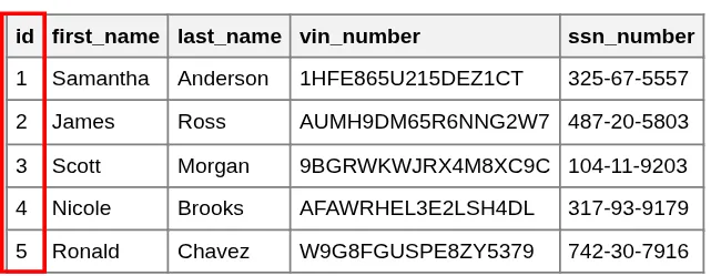
Imagine we are building a system to track traffic violations. A naive approach might be to put all the information—the driver's details and the violation details—into a single "big table." However, this approach quickly reveals a major flaw: redundancy.
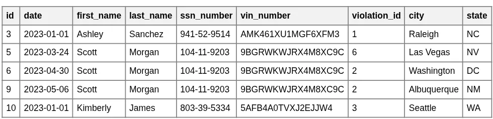
Initial Big Table
Redundancy Highlighted (Scott Morgan)
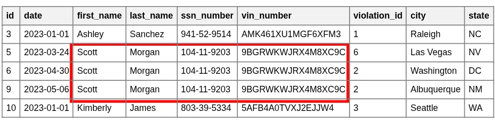
As shown in the highlighted example, Scott Morgan's name, VIN, and SSN are stored multiple times—once for every violation he commits. This design creates several problems:
- Update Anomalies: If Scott changes his name or we find a typo in his SSN, we must update every single row. Missing even one row results in inconsistent data.
- Storage Inefficiency: Storing long strings (like names and VINs) repeatedly wastes significant disk space.
- Performance Degradation: Larger tables are slower to search, scan, and process. As the data grows, retrieval operations become increasingly sluggish.
2. The Solution: Splitting the Tables
To solve these issues, we apply normalization by splitting the data into two distinct logical entities: Drivers and Traffic Violations.
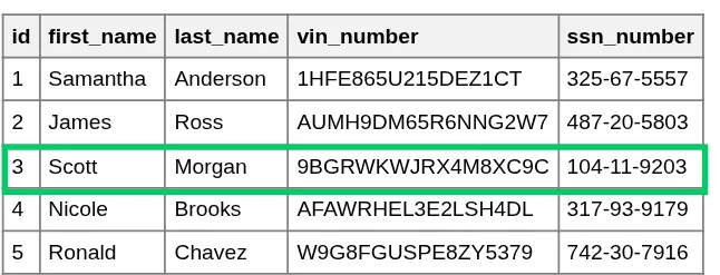
Drivers Table
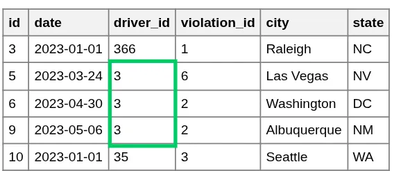
Traffic Violations Table
By separating these entities, we achieve a "Single Source of Truth." Scott Morgan's personal information is now stored exactly once in the Drivers table, regardless of whether he has one violation or one hundred. This makes the database cleaner, smaller, and much easier to maintain.
Connecting with a Foreign Key
Separating the tables is only half the battle; we still need a way to link them back together. We achieve this using a Foreign Key.
- Primary Key: In the Drivers table, each driver is assigned a unique
id. - Foreign Key: In the Traffic Violations table, we add a
driver_idcolumn. This column "points" to theidof the driver who committed the violation.
Driver ID (Scott Morgan = 3)
Violations pointing to ID 3
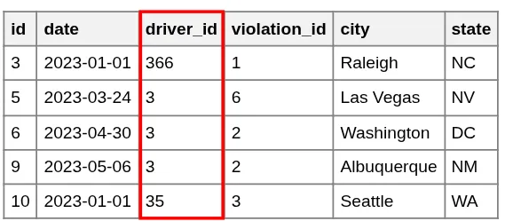
Now, instead of duplicating Scott's entire profile, we simply store the integer 3. If we ever need to see Scott's name for a specific violation, we use a JOIN operation to fetch it from the Drivers table using that ID. This ensures that any update to the Drivers table is instantly reflected across all related violations.
3. Why the Foreign Key is on the "Many" side?
A point of confusion for beginners may be deciding which table should hold the reference. Why don't we put a list of violations in the Drivers table?
Trying to put the relationship on the "One" side (Drivers) leads to two highly inefficient designs:
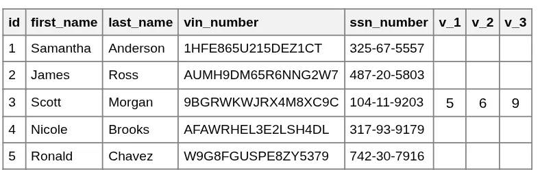
- Fixed Column Limits: If we add columns like
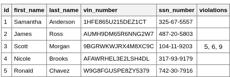
violation_1,violation_2, etc., what happens when a driver commits their 11th violation? We would have to change the entire table structure. - Unstructured Data: Storing a list of IDs in a single cell (like "101, 105, 210") makes it impossible for the database to efficiently search, index, or enforce rules on those violations.
By placing the Foreign Key on the "Many" side (Violations), we can have an unlimited number of violations for a single driver without ever changing the table schema.
Problem: Too many columns
Problem: Indeterminate cell size
4. Visualizing the Relation: Notations
When designing databases, engineers use Entity Relationship Diagrams (ERD). There are two primary ways to visually represent a One-to-Many connection.
Classic Notation
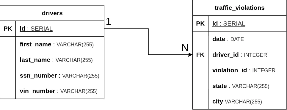
Classic notation uses a simple line or arrow labeled with 1 on the "One" side and N (or sometimes M) on the "Many" side.
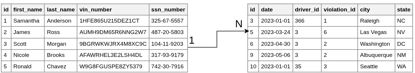
Here is how our specific Drivers-to-Violations relationship appears in the ERD diagram, where we typically present tables with their column names and data types instead of sample data rows.
Crow's Foot Notation
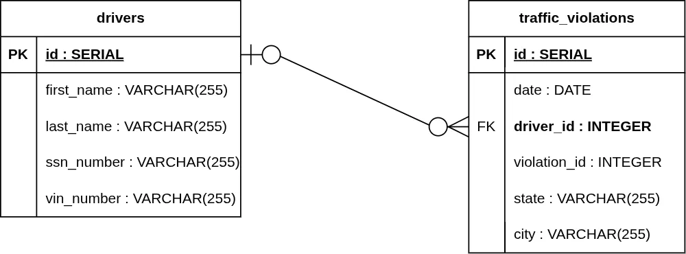
Crow's Foot Notation is the industry standard for modern ERDs. The "three-pronged" foot symbolizes the "Many" side, while vertical bars and circles represent mandatory or optional relationships.
In formal Crow’s Foot notation, every end of a relationship line must have two symbols: an inner symbol and an outer symbol (totaling 4 symbols for the entire relationship).
- The Inner Symbol (Modality): Defines the minimum cardinality. It indicates whether the relationship is optional (0) or mandatory (|).
- The Outer Symbol (Cardinality): Defines the maximum cardinality (1 or Many).
There are four primary configurations based on whether the ends are mandatory or optional:
1. Mandatory One to Mandatory Many (1..1 to 1..*)

Both sides are required.
- One Side: Two vertical lines (||). One instance of Entity B must have exactly one Entity A.
- Many Side: A vertical line and a Crow's Foot (| ∈). One instance of Entity A must have at least one Entity B.
Example: A traffic_violation record must be linked to exactly one driver, and a driver must have at least one traffic_violation record in the system to be tracked.
2. Mandatory One to Optional Many (1..1 to 0..*)

The "One" side is required, but the "Many" side is not.
- One Side: Two vertical lines (||).
- Many Side: A circle and a Crow's Foot (O ∈).
Example: A traffic_violation must belong to exactly one driver, but a driver can exist in the database without having any traffic_violations (a clean record).
3. Optional One to Mandatory Many (0..1 to 1..*)

The "One" side is optional, but the "Many" side is required.
- One Side: A circle and a vertical line (O|).
- Many Side: A vertical line and a Crow's Foot (| ∈).
Example: A traffic_violation can optionally be linked to a driver (e.g., a camera caught a speeding car but the driver hasn't been identified yet), but if a driver is present, they must have at least one traffic_violation record associated with them.
4. Optional One to Optional Many (0..1 to 0..*)
Both sides are optional.
- One Side: A circle and a vertical line (O|).
- Many Side: A circle and a Crow's Foot (O ∈).
Example: A traffic_violation can exist without an identified driver, and a driver can exist in the database without any registered traffic_violations.
5. Implementation in PostgreSQL
Now, let's look at the actual SQL implementation. The magic happens with the REFERENCES keyword, which tells the database that these two tables are linked.
Why use REFERENCES?
By marking the driver_id column as a REFERENCE to the drivers(id) column, we enable Referential Integrity.
PostgreSQL acts as a "guardian" of your data:
- If you try to add a violation for a
driver_idthat doesn't exist in thedriverstable, or - if you try to delete a driver who still has active violations, PostgreSQL will block the operation.
This prevents "orphaned" records and ensures your database never becomes a mess of disconnected information.
Handling Deletions with CASCADE
We can also configure the relationship to allow the removal of a driver even if they have records in the traffic_violations table. Using ON DELETE CASCADE will automatically remove all associated violations when a driver is deleted.
There are two ways to implement this, depending on whether the tables already exist.
Option 1: Updating an existing table
If the tables were already created as shown above, you must drop the current constraint and add a new one with the CASCADE option:
Option 2: Creating a new table
If you haven't created the traffic_violations table yet, you can include the instruction directly in the definition:
Enforcing Modality in SQL
In a SQL database, Crow's Foot modality is controlled by NOT NULL constraints on the Foreign Key.
Mandatory Modality: A violation must have a driver:
Optional Modality: A violation can exist without a driver (e.g., an anonymous violation):
Loading the Data
With the structure in place, we can load our sample data from CSV files.
6. One-to-Many Relationships in Tableau
When working with data visualization in Tableau, defining relationships is critical for accurate analysis. Here is how our drivers.csv and traffic_violations.csv datasets are connected.
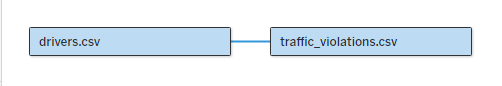
Defining the Logical Relationship: In Tableau's Data Source tab, we drag the drivers and traffic_violations tables into the canvas. By connecting them, Tableau creates a "noodle" (logical relationship).
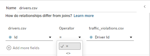
Mapping Foreign Keys: Here, we explicitly tell Tableau which columns form the link. We select the Primary Key (id) from the drivers source and the Foreign Key (driver_id) from the traffic_violations source. This ensures that every violation is correctly attributed to the right driver during visualization.
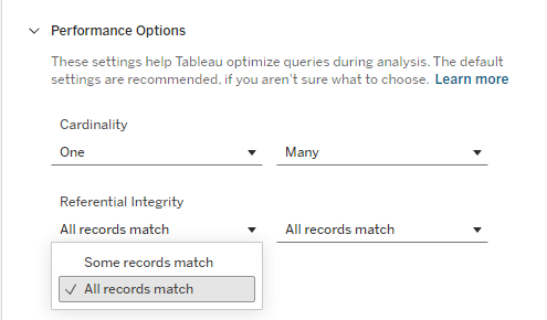
Performance Options (Cardinality): In the "Performance Options" settings, we can optimize the relationship. We set Cardinality to One-to-Many (One driver to Many traffic_violations). We also configure Referential Integrity to "All records match". ( "Some records match," would be appropriate if we have drivers without violations or anonymous violations.) These settings help Tableau generate more efficient SQL queries.
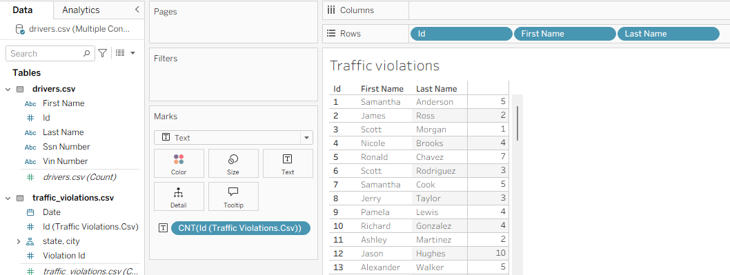
Verifying the Relationship: Once the relationship is established, we can easily create visualizations. For example, by dragging Id, First Name, and Last Name from the drivers table to the Rows shelf and Id from the traffic_violations table to the Text mark (in the Marks card), then setting its aggregation to Count, Tableau automatically performs the equivalent of a LEFT JOIN and a `GROUP BY`. This allows us to see exactly how many violations each driver has accumulated.